The Uni E-Bike (University E-Bike) is a project inspired by laziness. During freshman year of college, I would bike to every class. I liked doing this because I could leave 10 minutes before class and get there with time to spare. One problem with biking, however, is that it requires energy and hot days create a sweaty situation. Particularly, there is one hill on campus that would kill my momentum every single morning. I had heard of electric bikes, but one quick Google search had my wallet begging me to find an alternative. So, as any sane person would do, I decided to build my own!
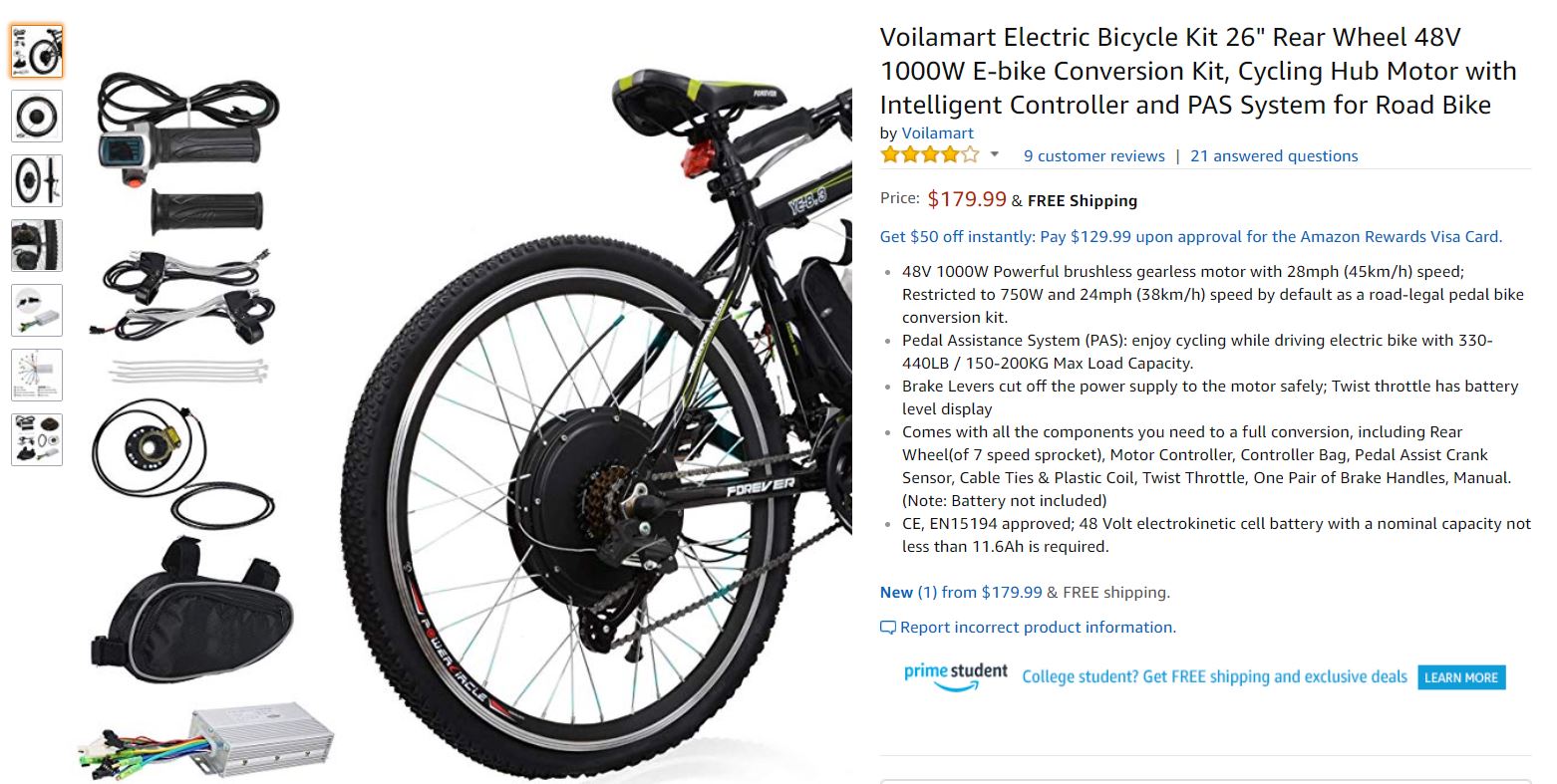
The first step was to find a motor. The two main options were to have an independent motor with a chain connected to the wheel, or have the motor built in to the wheel itself. I chose a hub motor design so I could still pedal with the motor running/not running, and to keep the bike as discrete as possible. The hub chosen can be seen below.
Next, I had to figure out how to power the motor. After researching different batteries on the market, I chose to create my own battery pack. Yes, from scratch. This reasoning came from the simple fact that no battery on the market today could accomplish all of my design constraints. I wanted a battery that I could house in my backpack while riding. A design like this would allow me to charge the battery in class if the power got to low, and prevent any theft for the bike. The battery is the most expensive part of the build, so theft prevention was at the top of the priority list. These constraints called for a small, lightweight battery, and I could not find any battery cheap enough.
To create a battery, I needed three main components: battery cells, a battery management system (BMS), and a way to connect everything together. For battery cells, I chose to use 18650 cells. These are the same type of battery cell used in Tesla battery packs, so I figured they’re a pretty safe bet. Each battery cell is rated for 3.6V and 3000 mAh. I purchased a 36V motor, so I needed 30 cells to reach the required voltage and run-time. The cells are wired in a 10s3p configuration (10 in series, 3 in parallel). This means there are 10 groups of three cells.
Next, I needed a battery management system (BMS). A battery management system allows and regulates charging. It stands as a safety measure so no battery gets overcharged, and makes sure charging stays equal over the entire battery pack. The cells and the BMS are connected via nickel strips and solder. Whilst doable, this method is not the most effective, nor the safest way of wiring. The battery pack (outside its housing) can be seen below.
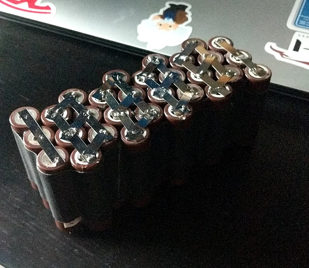
While it isn’t the prettiest job in the world, it’s my job and I am proud of it!
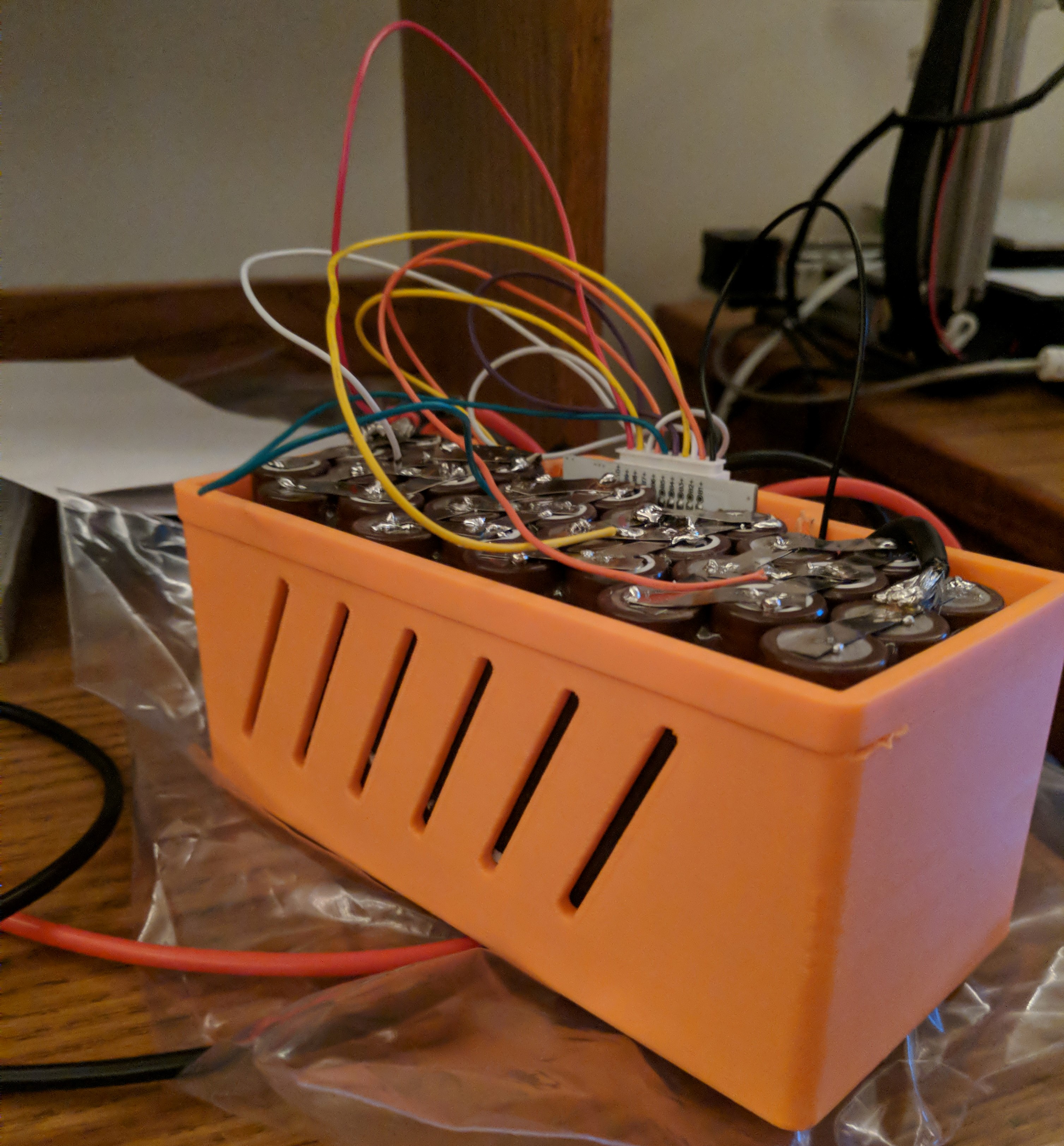
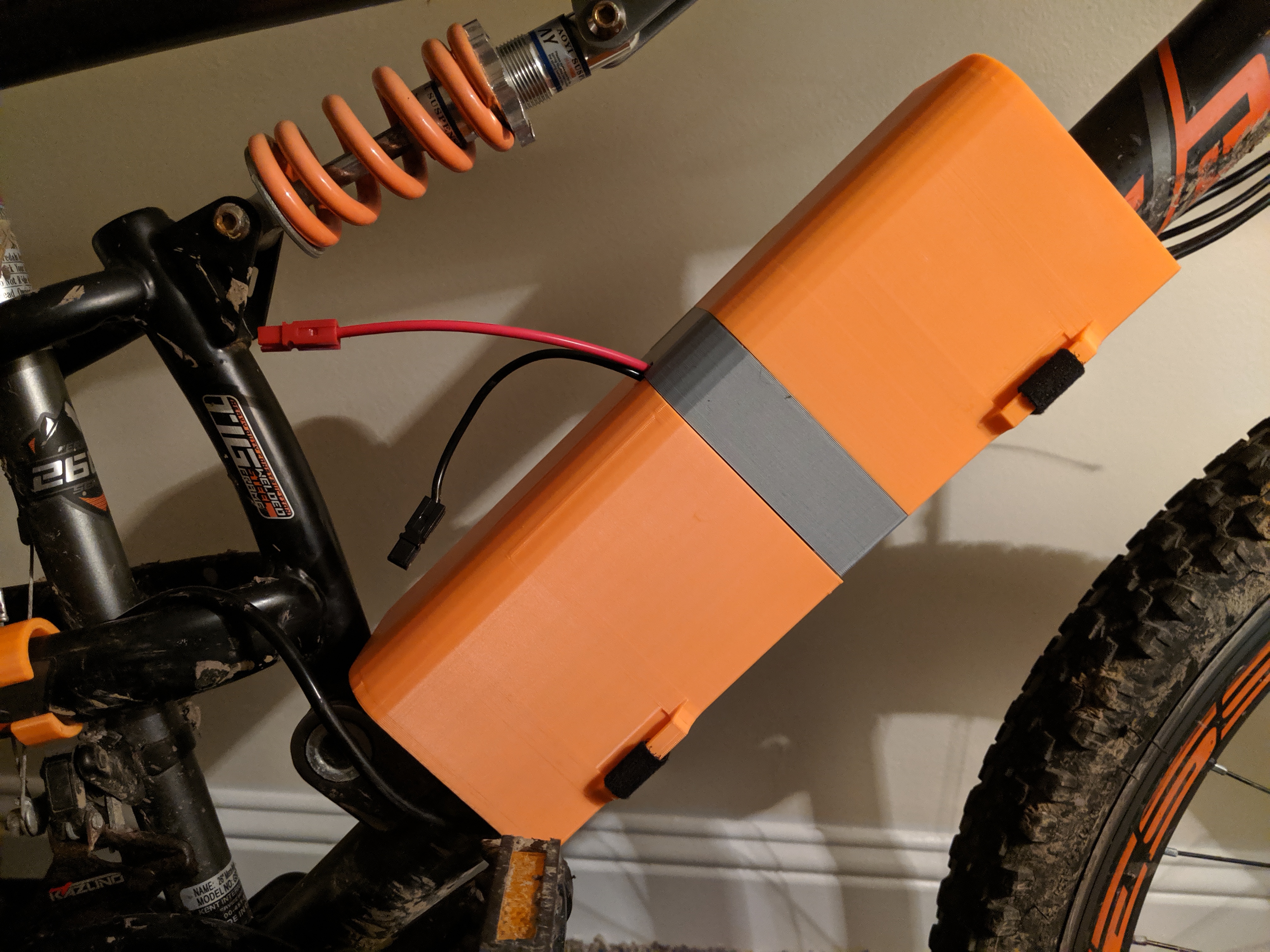
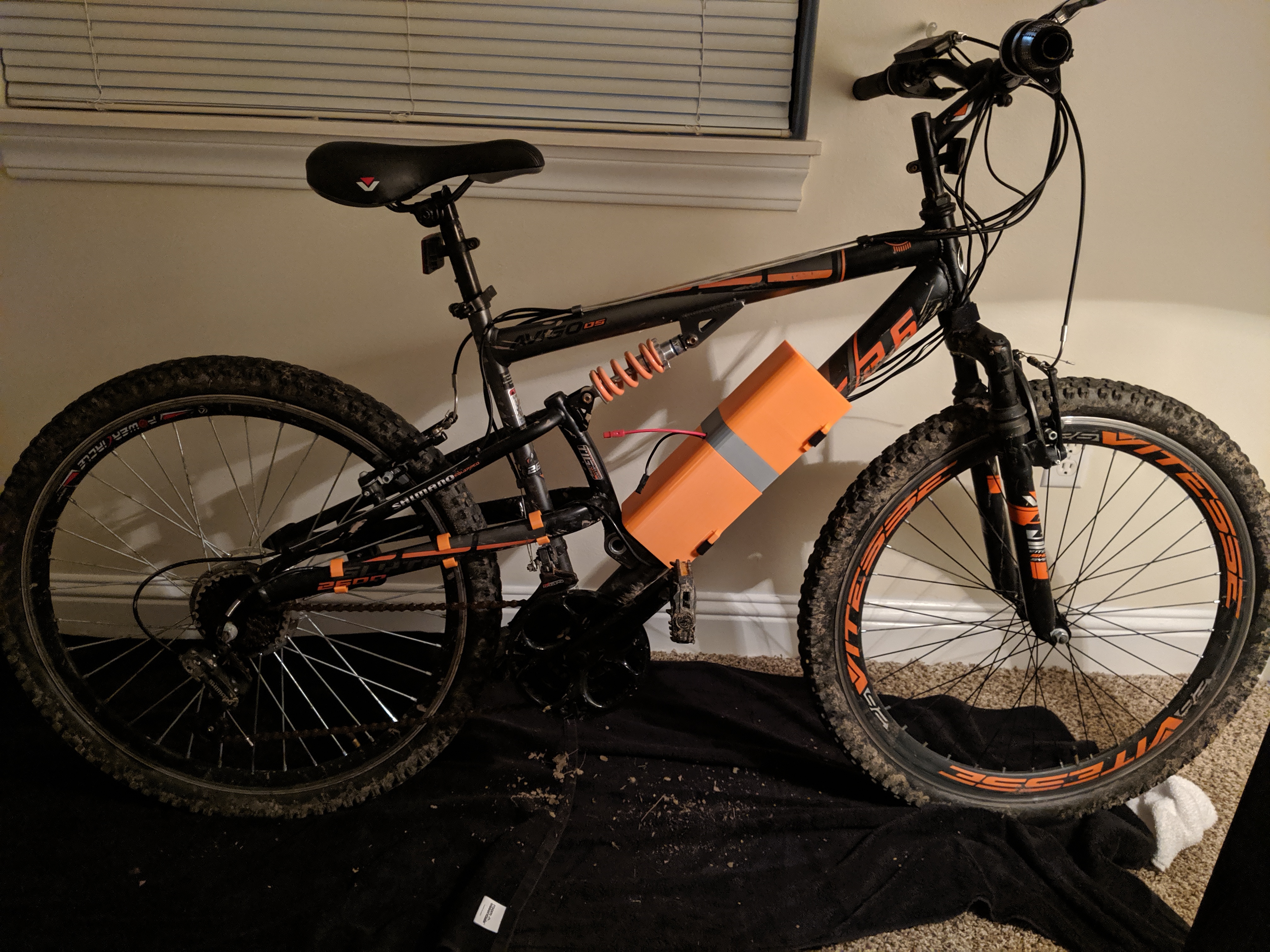
After the battery pack was finished, which took absolutely ages, it was time to make a housing for it. This was the easy part considering I love 3D modeling/printing. I created the housing with slits to reduce heat build-up inside my backpack. The design ended up looking like a mock-up for a new building in Washington D.C. This was not my intention, but I welcome the vibe.
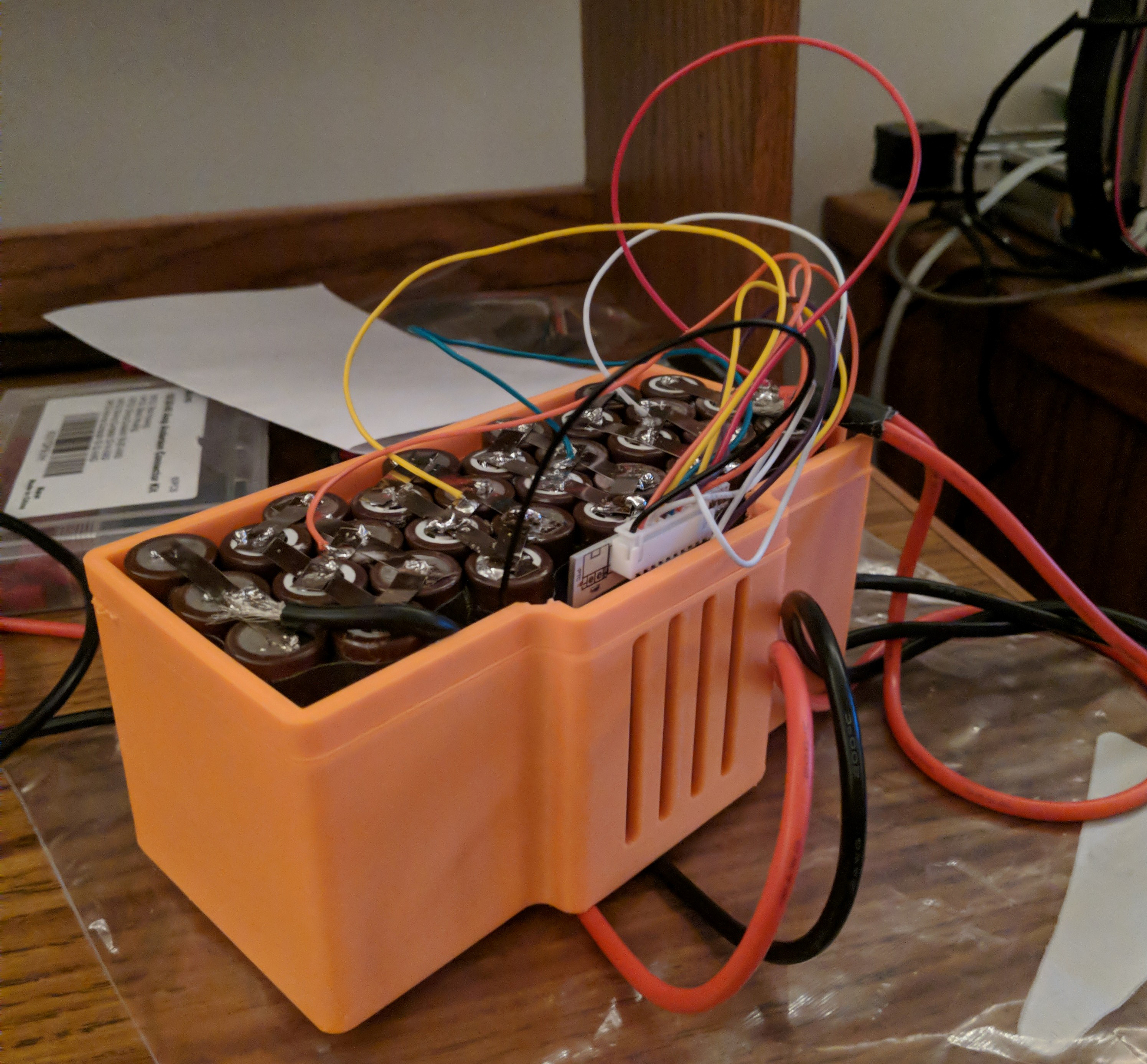
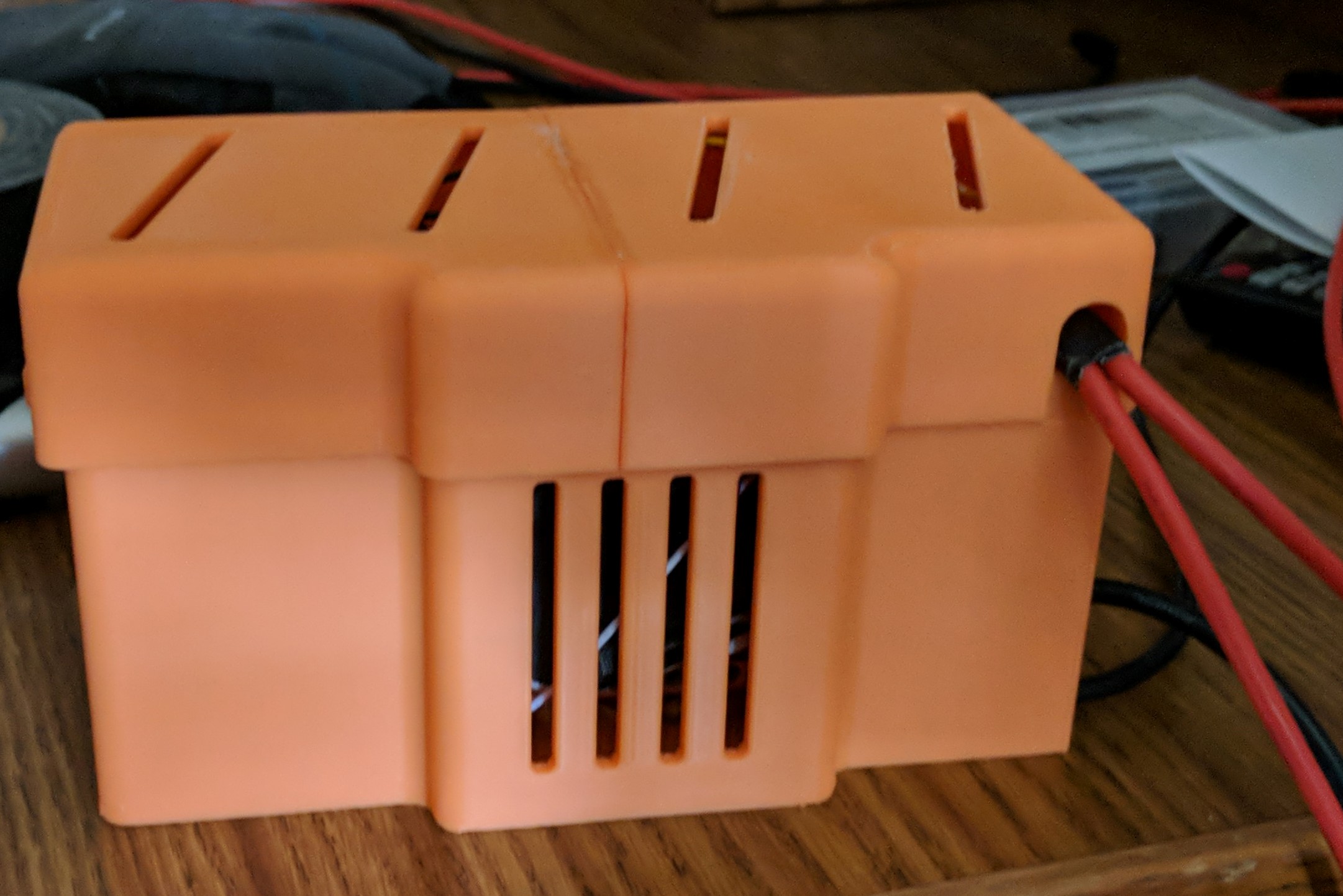
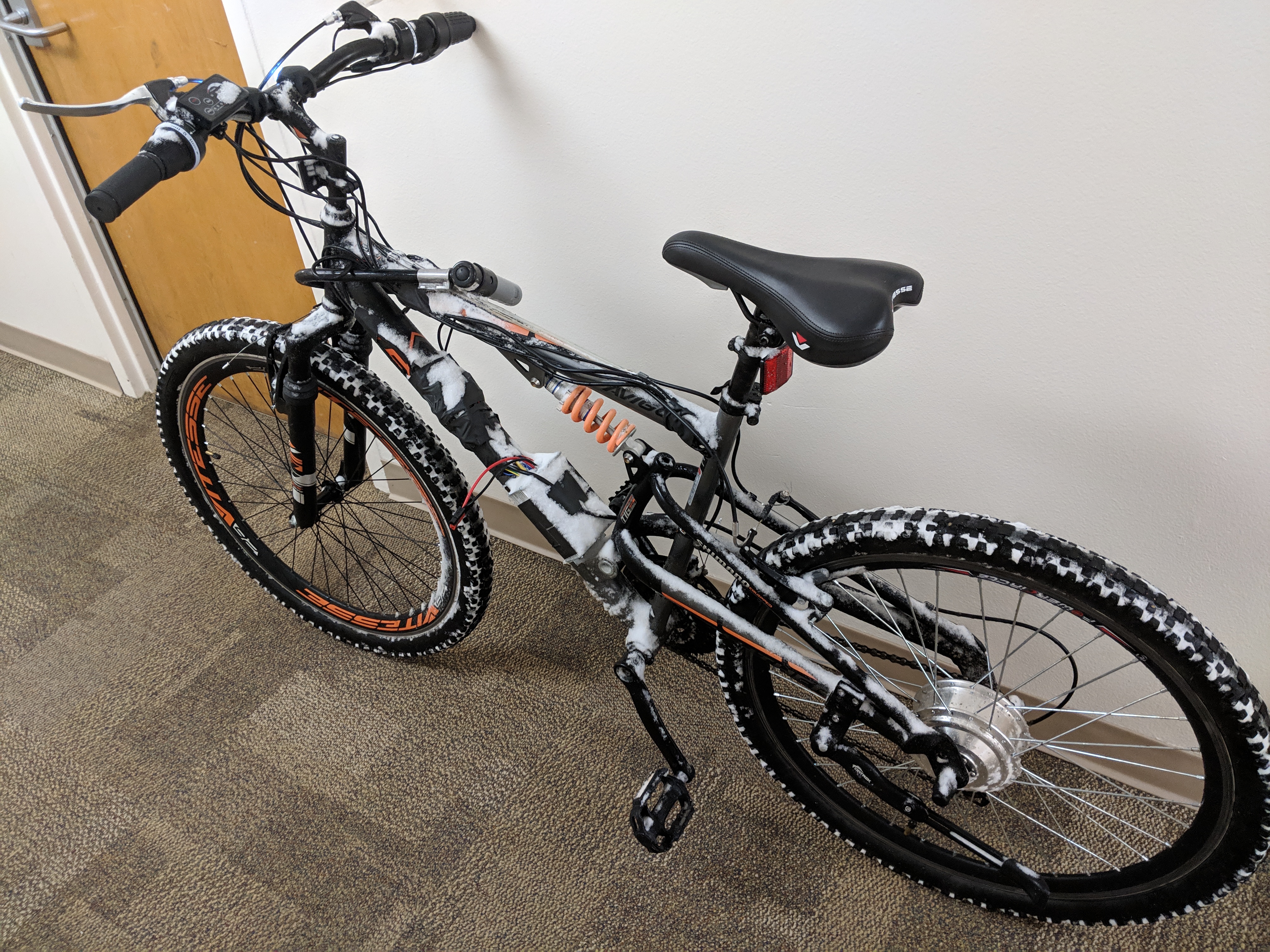
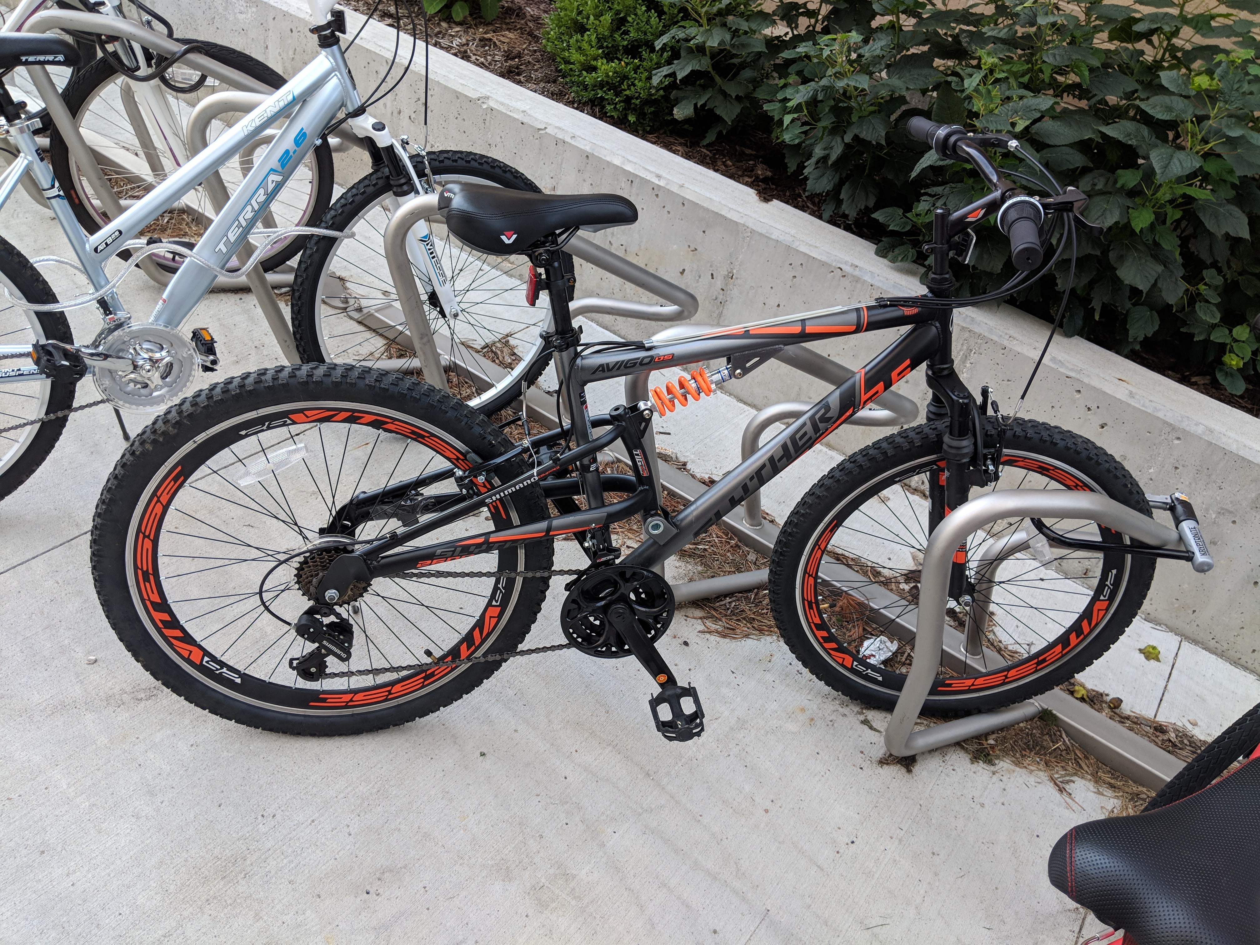
One red wire and black wire (seen in the picture above) come out of the battery and plug directly into the wheel hub controller. These wires are about 5 feet long, because they have to span from my backpack all the way to the center housing of the bike, and have slack. I put quick release connectors on both wires in the case of an emergency ejection situation. The controller acts as a hub for all connections and houses the main motherboard for the motor. The wires from the wheel run up the side of the bike and into the controller. There are two wires spanning all the way to the handlebars and into both brake levers. When the brakes are pulled, all power is cut from the motor. This safety feature ensures that if there is a shut-off in case of a stuck throttle situation. The throttle is a twist throttle set-up like a motorcycle. The picture below shows the general set-up of the bike.
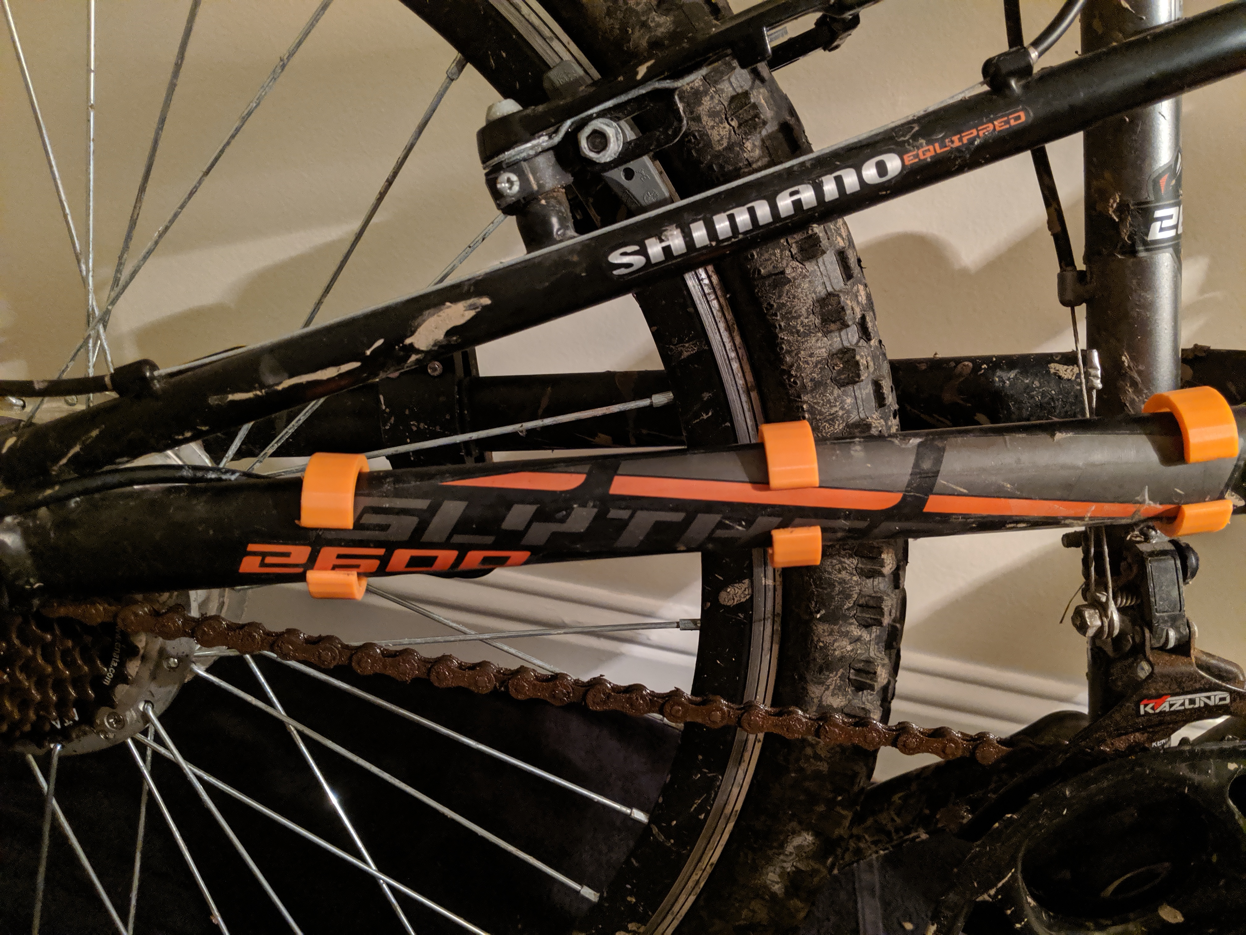
Once everything was installed on the bike, I modeled and printed a cover for the motor controller as well as clips for the wires running from the wheel to the controller. The covers slim up all of the loose wirings and makes the whole system water-resistant.
Finally, the bike was ready to ride. I rode the bike for the first time and it was running great! Until about 15 minutes in, when it blew its back tire! What a wonderful first test..
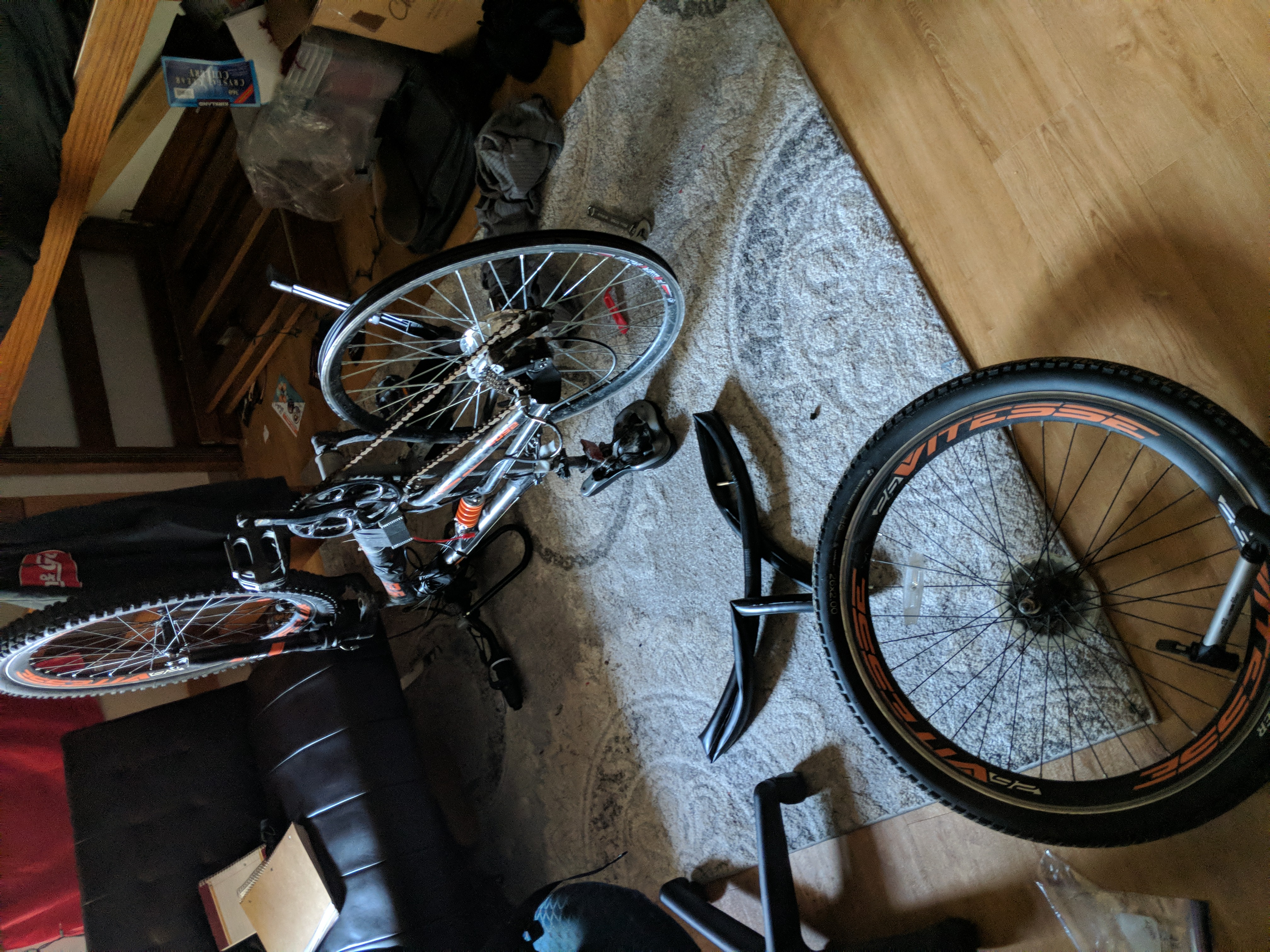
After getting the tire fixed, I went on another test run and everything went according to plan! The bike runs about 20 mph without any pedal assistance and on flat ground. With pedal assistance, you can get about 30 mph in a higher gear. This is more than enough speed, especially on a college campus. As for the battery, it actually lasts longer than I predicted! I can go 2 or 3 days of school without needing a charge. The size is perfect for my backpack, but I do get some weird looks walking into class with 2 wires coming out of my backpack. The total cost of this build ended up being just around $400. Without mistakes, this could easily have been a $350 or less build. Either value is still dramatically less than its market equivalent. Since the build has finished, I have yet to have any issues with the bike. Over the summer of 2019, I was working out in Ohio and actually took the bike on some beginner mountain biking tracks. Both times I went, I wiped out multiple times. I really put those quick-release battery connectors to use! I now have a GoPro on my helmet so I can capture my fails from now on.
All in all, this project was very successful. I met my goals and even exceeded them in some areas. I do wish I could have done it in a smaller time table, but college took priority. I learned a TON about batteries and soldering during this process, and I know what I need to do next time I make a battery. To end it off, I’ll leave a before and after picture below. Thank you for reading this and I look forward to whatever project I work on next!
E-Bike